FIGURE A
SAMPLE SCHEMATIC DRAWING
**Be sure to add the pipe size for each run/length of piping
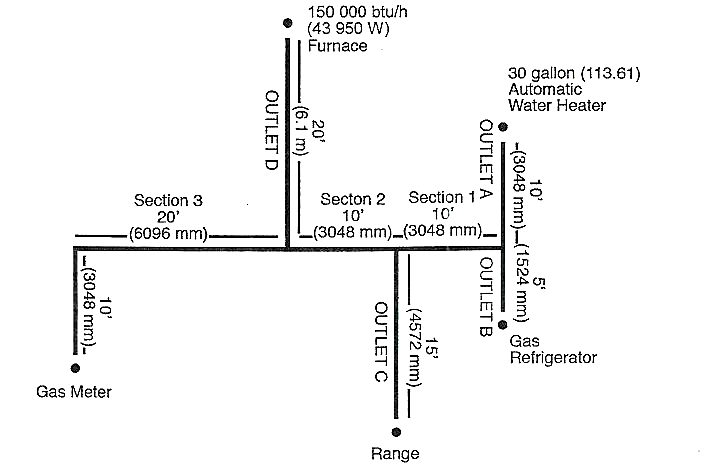
- Compute CFM demand for all appliances
- Maximum gas demand of outlet A:
- 32 cubic feet per hour (from Table 1).
- Maximum gas demand of outlet B:
- 3 cubic feet per hour (from Table 1).
- Maximum gas demand of outlet C:
- 59 cubic feet per hour (from Table 1).
- Maximum gas demand of outlet D:
- 136 cubic feet per hour [150,000 Btu/hour divided by 1100 Btu per cubic foot].
- Maximum gas demand of outlet A:
- Determine the length of pipe from the gas meter to the most remote outlet (outlet A) is 60 feet.
- Using the length in feet column row marked 60 feet in Table 2:
- Outlet A, supplying 32 cubic feet per hour, requires ½ inch pipe.
- Section 1, supplying outlets A and B, or 35 cubic feet per hour requires ½ inch pipe.
- Section 2, supplying outlets A, B, and C, or 94 cubic feet per hour requires 3/4 inch pipe.
- Section 3, supplying outlets A, B, C, and D, or 230 cubic feet per hour, requires 1 inch pipe.
- Using the column marked 60 feet in Table 2 [no column for actual length of 55 feet]:
- Outlet B, supplying 3 cubic feet per hour, requires ½ of an inch pipe.
- Outlet C, supplying 59 cubic feet per hour, requires ½ of an inch pipe.
- Using the column marked 60 feet in Table 2:
- Outlet D, supplying 136 cubic feet per hour, requires ¾ inch pipe.