
HYDROMECHANICAL GREASE
INTERCEPTOR (HGI), FLOW CONTROL,
AND FLOOR DRAIN INSTALLATION
2010 California Plumbing Code (CPC)
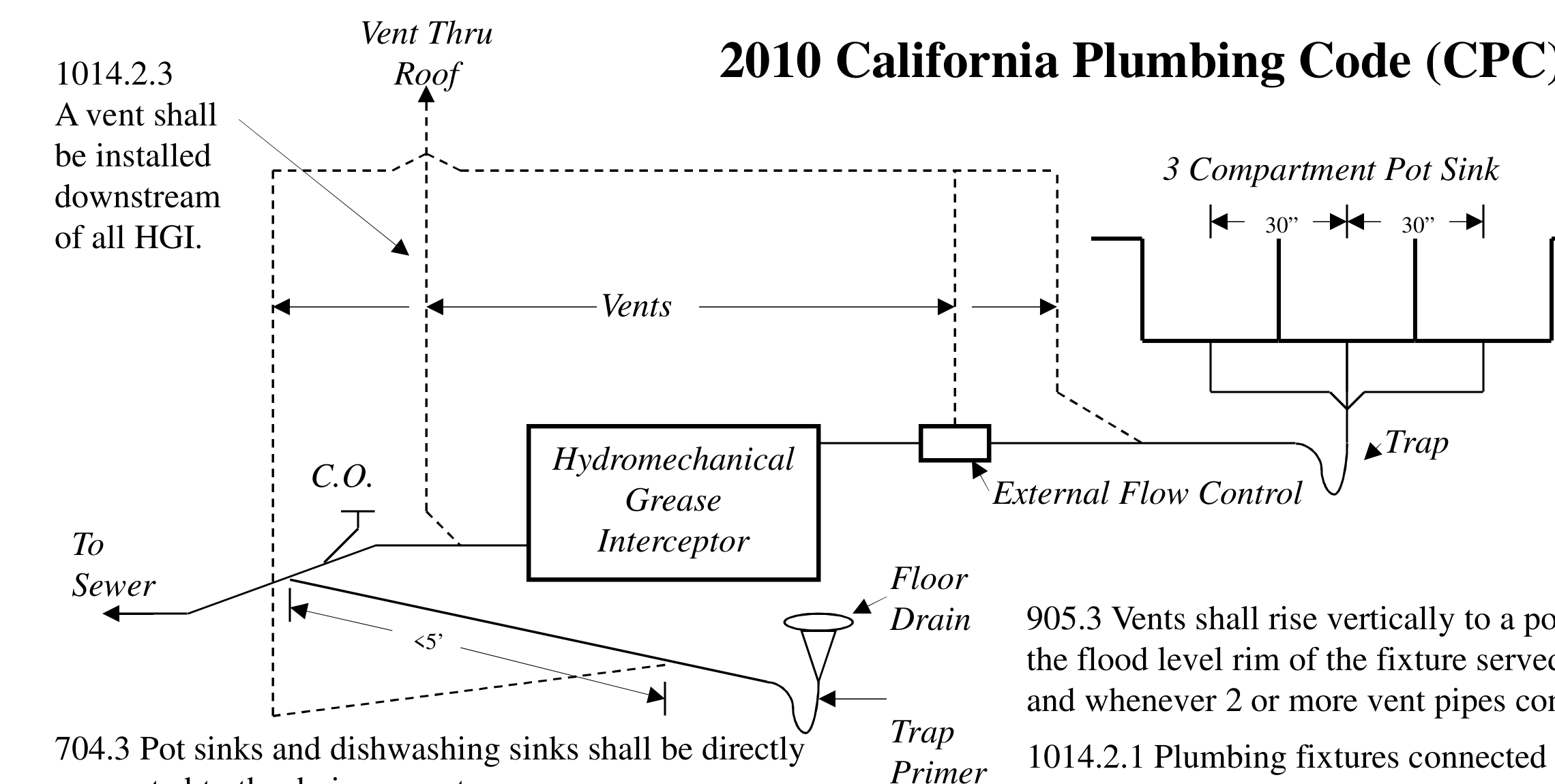
Floor drain shall be installed in commercial kitchens.
Pot sinks and dishwashing sinks shall be directly connected to the drainage system.
Pot Sinks – A floor drain shall be provided adjacent to the fixture and the fixture shall be connected on the sewer side of the floor drain trap provided that no other drainage line is connected between the floor drain waste connection and the fixture drain.
Horizontal drainage piping shall be provided with a cleanout at its upper terminal. When serving sinks, cleanouts shall not be omitted on horizontal drain lines less than 5 feet, unless the piping is above the floor level of the lowest floor of the building.
Vents shall rise vertically to a point not less than 6 inches above the flood level rim of the fixture served before offsetting horizontally and whenever 2 or more vent pipes converge.
One trap may serve not more than 3 single compartment sinks of the same depth immediately adjacent to each other and in the same room if the waste outlets are not more than 30 inches apart and the trap is centrally located when 3 compartments are installed.
Each fixture trap shall have a protecting vent.
Each fixture discharging into a HGI shall be individually trapped and vented.
Plumbing fixtures connected to a Type A and B HGI (A=external flow control with air intake vent, directly connected. B=external flow control without air intake vent, directly connected) shall discharge through an approved type of vented flow control installed in a readily accessible and visible location. Vented flow control shall be located such that no system vent shall be between the flow control and the grease interceptor inlet.
The term “fixture” shall mean and include each plumbing fixture, appliance apparatus, or other equipment required to be connected to or discharging into a HGI.
The total capacity in gallons of fixtures discharging into any HGI shall not exceed 2 ½ times the certified GPM flow rate of the interceptor as per CPC Tables 10-2.
A vent shall be installed downstream of all HGI.