630 Signing Misc.: Solar Powered & Wireless Rectangular Rapid Flashing Beacon (RRFB) Sign Assembly
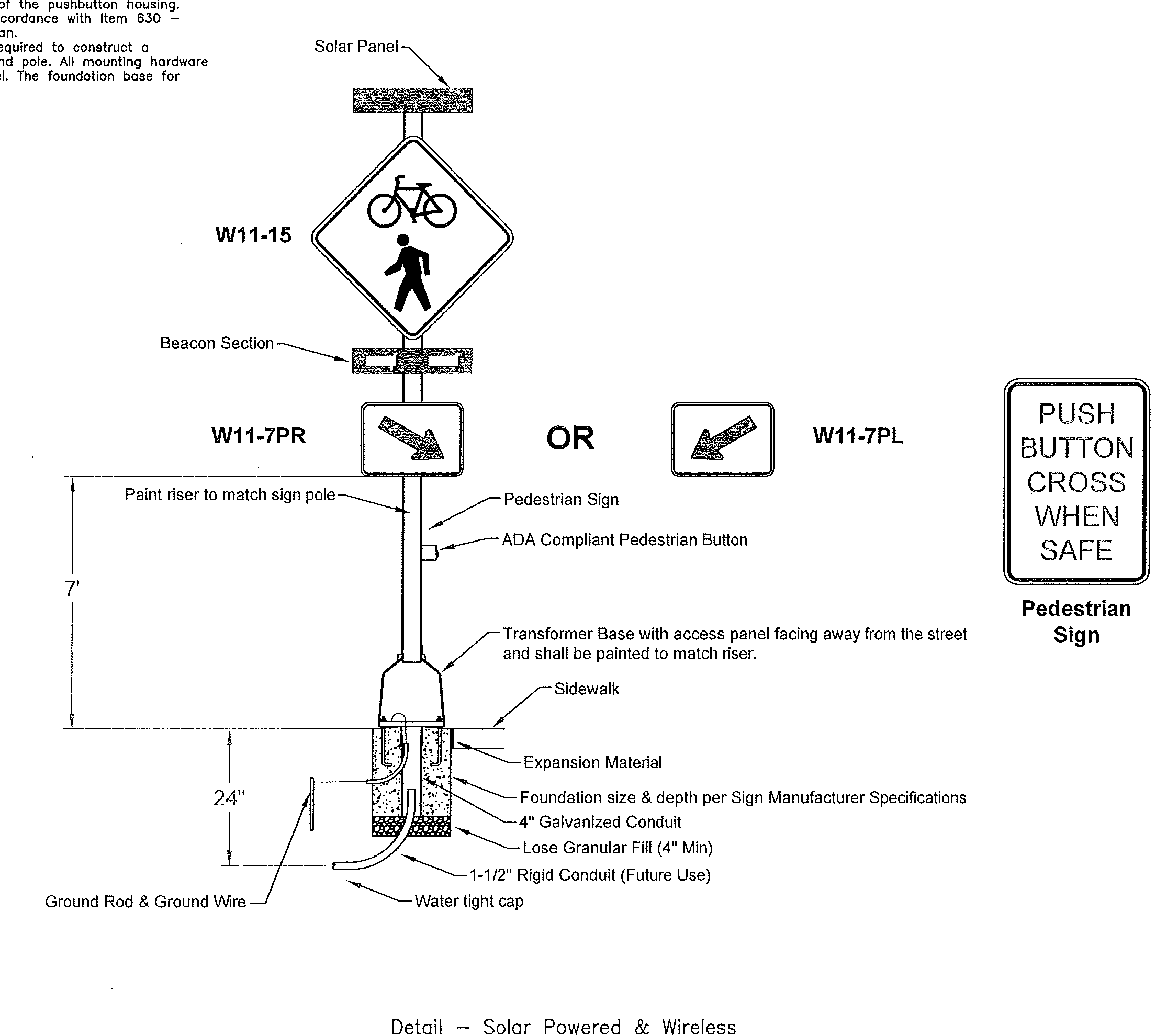
This work shall consist of furnishing and installing a solar powered Rectangular Rapid Flashing Beacon (RRFB) sign assembly. The flashing unit shall be 1-sided LED, solar powered and pedestrian activated. Multiple units shall be wirelessly controlled and synchronized. The unit shall be compliant with the most current Ohio Manual of Uniform Traffic Control Devices (OMUTCD).
General Requirements
- Each RRFB shall consist of two rapidly and alternately flashing rectangular yellow indications having LED array based pulsing light sources.
- Each RRFB shall be a complete assembly, consisting of but not limited to, signage, sign mounting hardware, indications and electrical components (wiring, solid-state circuit boards, etc.).
Functional Requirements
- Each RRFB shall utilize solar power.
- Each RRFB shall be activated by ADA compliant pushbuttons.
- The RRFB shall be normally dark, shall initiate operation only upon pedestrian activation, and shall cease operation after a predetermined time limit (based on OMUTCD procedures).
- Each remote RRFB shall be wirelessly activated.
- When activated, the RRFB unit indications shall flash in a rapidly alternating "wig-wag" flashing sequence (left light on, then right light on).
- All RRFB light indications shall be wirelessly synchronized (all lights will turn on within 120msec and remain synchronized throughout the duration of the flashing cycle).
- Each of the RRFB's indications shall flash at 70 to 80 flashes per minute.
- The unit shall be low current/high output including automatic dimming capabilities for day and night visibility.
- The unit shall be capable of running up to 30 days without sunlight.
Materials
Furnish a complete assembly, consisting of but not limited to, signage, sign mounting hardware, indications, and electrical components (wiring, solid-state circuit boards, etc.). The RRFB assembly includes the following items:
- 1. RRFB Indications
- a. Each RRFB indication lens shall be a minimum size of approximately 5" wide x 2" high.
- b. The RRFB indications shall be aligned horizontally, with the longer dimension of the indication horizontal. There shall be two indications on the front and two indications on the back.
- c. Each RRFB shall be supplied with all required hardware to install assembly. All exposed hardware shall be anti-vandal.
- d. The RRFB shall be located between the bottom of the crossing warning sign and the top of the supplemental downward diagonal arrow plaque.
- e. The light intensity of the yellow indications shall meet the minimum specifications of Society of Automotive Engineers (SAE) standard J595 (Directional Flashing Optical Warning Devices for Authorized Emergency, Maintenance, and Service Vehicles) dated January, 2005.
- f. A small confirmation light directed at and visible to pedestrians in the crosswalk shall be installed integral to the RRFB or pushbutton to give confirmation that the RRFB is in operation.
- 2. Signs
- a. All sign assemblies shall use anti-vandal fasteners to mount components to sign and sign to fixture.
- b. Pedestrian pushbuttons signs shall be provided and include the legend "PUSH BUTTON TO TURN ON WARNING LIGHTS". Signs should be mounted adjacent to or integral with each pedestrian pushbutton.
- 3. Control Circuit
- a. When activated, the two yellow indications in each RRFB shall flash in a rapidly alternating "wig-wag" flashing sequence (left light on, then right light on).
- b. The control circuit shall have the capability of independently flashing up to two independent outputs. The LED light outputs and flash pattern shall be completely programmable.
- c. As a specific exception to the 2003 MUTCD Section 4K.01 requirements for the flash rate of beacons, RRFBs shall have a much faster flash rate. Each of the two yellow indications of an RRFB shall have 70 to 80 periods of flashing per minute and shall have alternating, but approximately equal, periods of flashing light emissions and dark operation. During each of its 70 to 80 flashing periods per minute, the yellow indications on the left side of the RRFB shall emit two slow pulses of light after which the yellow indications on the right side of the RRFB shall emit four rapid pulses of light followed by a long pulse.
- d. The flash rate of each individual yellow indication, as applied over the full on-off sequence of a flashing period of the indication, shall not be between 5 and 30 flashes per second, to avoid frequencies that might cause seizures.
- e. The control circuit shall be sealed watertight to eliminate dirt contamination and allow for safe handling in all weather conditions.
- f. The LEDs shall be sealed against dust and moisture intrusion as per the requirements of NEMA Standard 250-1991 for Type 4 enclosure and to protect all internal LED and electrical components.
- g. Communication between same direction RRFBs shall be done wirelessly.
- 4. Battery and Solar Panels
- a. Battery unit shall be a 12VDC, 40 AHr minimum, sealed GEL or AGM lead acid battery. Batteries shall have a written two year full replacement warranty.
- b. The solar panel shall provide a minimum of 55 watts peak total output.
- c. The solar panel shall be mounted to an aluminum plate and bracket at an angle of 45 degrees – 60 degrees to provide maximum output.
- d. All fasteners used shall be anti-vandal.
- 5. Wireless Radio
- a. Radio control shall operate on a 900 MHz frequency hopping spread spectrum network, Wi-Fi or approved equal.
- b. Radio shall integrate communication of RRFB control circuit to activate sign from pushbutton input.
- c. The radio shall be synchronized so all of the remote RRFB light indications will turn on within 120 msec of each other and remain synchronized through-out the duration of the flashing cycle.
- d. Radio systems shall operate from: 3Vdc to 15Vdc.
- 6. Pushbutton
- a. The pushbutton shall be capable of continuous operation over a temperature range of -30 degrees F to +165 degrees F.
- b. Pushbutton shall be ADA compliant.
- c. Pedestrian buttons shall be installed at plan locations to provide pedestrian actuation of the signal.
- d. Pushbuttons are to be mounted 36"-42" above adjacent sidewalk.
- e. Pushbuttons shall be pressure activated with non-moving button and provide both a two-tone audible beep and a visible, momentary LED to notify the user that the switch was activated.
- f. An acceptable pushbutton shall be the Bull Dog, manufactured by Polara Engineering, Inc., or approved equal.
- g. The outer housing color shall be black and the button shall be silver.
- h. A clear bead of silicon sealant shall be applied to the top of the pushbutton housing and the pole (1 inch each to each side from the top center of the housing) to prevent water from entering the back of the pushbutton housing.
- 7. Each transformer base and riser shall be painted in accordance with Item 630 – Sign Support, Type TC-16.21, Design No. 6, As Per Plan.
- 8. Payment. Each RRFB assembly shall include all items required to construct a functioning assembly, including the transformer base and pole. All mounting hardware used to construct this assembly shall be stainless steel. The foundation base for each assembly shall be paid for separately.
CALCULATED: SAB
CHECKED: GEI
MOT-CR-609 SHROYER ROAD IMPROVEMENTS
GENERAL NOTES & DETAILS
CITY OF KETTERING
3600 Shroyer Road, Kettering, Ohio 45429 | www.ketteringoh.org
Sheet: 02-124i
4 / 54