1. Site Survey, Grading Adjustment & Softball Netting Layout Plan
Scroll horizontally to view complete drawing details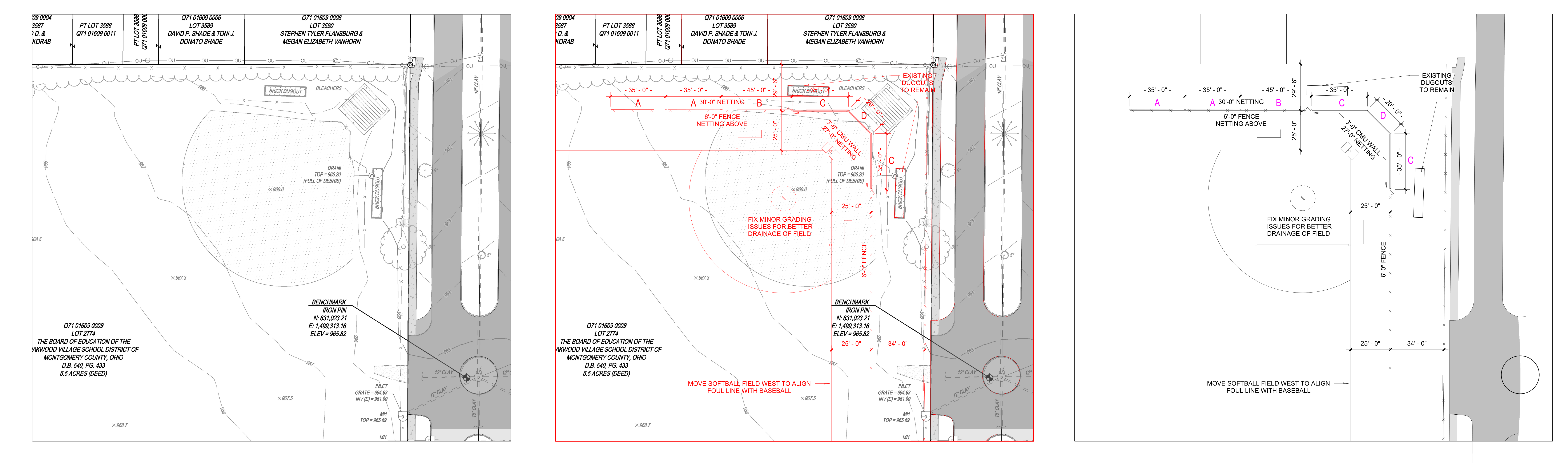
2. Netting Elevation Panels (Field Side)
Scroll horizontally to view complete elevation panels
3. Connection Hardware, Direct Bury Footing & Backstop Fan Side Elevations
Scroll horizontally to view complete hardware and foundation details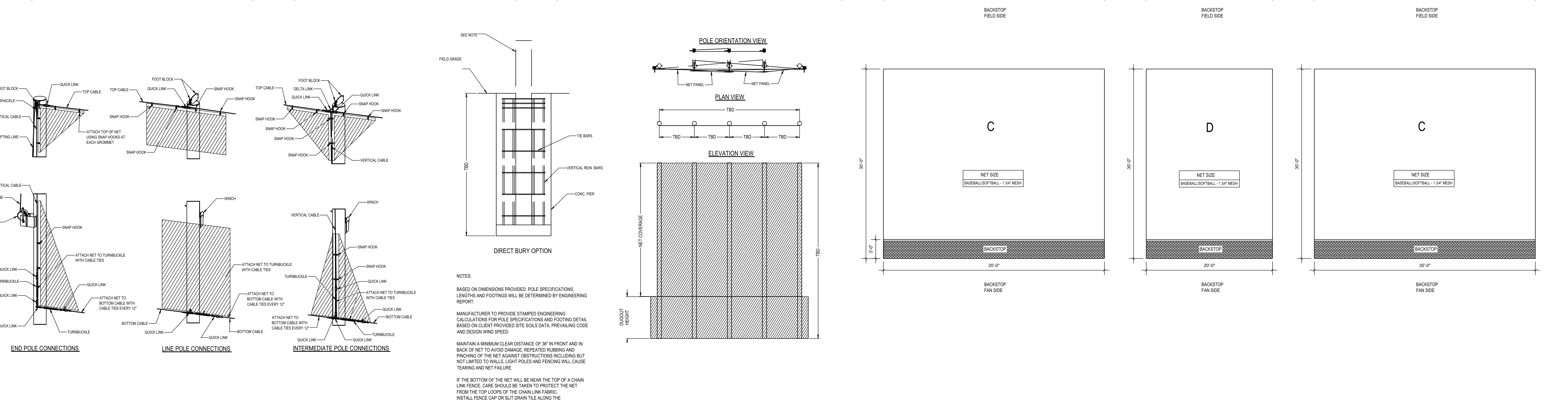
Accessible view
Protective Netting Specifications & Layout Data
Site survey, grading adjustment & softball netting layout
- The layout sequence is A, A, B, C, D, C from left to right. The dimensioned widths are 35'-0", 35'-0", 45'-0", 35'-0", 20'-0", and 35'-0", respectively.
- The netting is shown as 30'-0" netting above the lower condition. The lower condition is 6'-0" chain link fence at panels A, A, and B; panels C, D, and C are shown over a 3'-0" CMU wall with navy pads, leaving 27'-0" of net above the wall.
- The site drawing includes an existing-conditions plan, a red annotated/proposed alignment plan, and a simplified layout diagram. It labels existing dugouts to remain, shows 25'-0", 25'-0", and 34'-0" dimensions in the layout, and calls for minor grading corrections for better field drainage.
- The benchmark is an iron pin at N: 631,023.21, E: 1,499,313.16, ELEV = 965.82. The softball field is to move west to align the foul line with baseball.
Connection hardware, direct-bury footing & anchorage
- The hardware drawing has separate details titled END POLE CONNECTIONS, LINE POLE CONNECTIONS, and INTERMEDIATE POLE CONNECTIONS. The details show the net attached along the pole/cable system at the end, line, and intermediate pole conditions.
- The DIRECT BURY OPTION is shown as a vertical pole extending below field grade into a concrete footing. The detail labels the field grade, vertical rebar, concrete, and tie rods; the footing and pole specifications are subject to the engineering notes.
- POLE ORIENTATION VIEW, PLAN VIEW, and ELEVATION VIEW show the pole/anchor arrangement, repeated pole bays, and the net plane in relation to the field side. The drawing notes that pole specifications, lengths, and footings are to be determined by the engineer.
Backstop fan-side elevations
- The three panels are labelled C, D, and C and are identified as BACKSTOP FAN SIDE. Their widths are 35'-0", 20'-0", and 35'-0", respectively.
- Each fan-side panel shows a 3'-0" lower CMU wall with navy pads and 30'-0" total net height, including 27'-0" of net above the wall.
Swipe or scroll horizontally to view all columns.
| Panel ID | Width | Net Height | Base / Lower Wall | Mesh Size | Orientation / Notes |
|---|---|---|---|---|---|
| A (Left) | 35'-0" | 30'-0" | 6'-0" Chainlink Fence | 1 3/4" Mesh (Baseball/Softball) | Foul line sideline coverage |
| A (Left Center) | 35'-0" | 30'-0" | 6'-0" Chainlink Fence | 1 3/4" Mesh (Baseball/Softball) | Foul line sideline coverage |
| B (Center-Left) | 45'-0" | 30'-0" | 6'-0" Chainlink Fence | 1 3/4" Mesh (Baseball/Softball) | Adjacent to existing dugouts |
| C (Center-Right) | 35'-0" | 30'-0" (27'-0" above wall) | 3'-0" CMU Wall w/ Navy Pads | 1 3/4" Mesh (Baseball/Softball) | Backstop wing section |
| D (Center Backstop) | 20'-0" | 30'-0" (27'-0" above wall) | 3'-0" CMU Wall w/ Navy Pads | 1 3/4" Mesh (Baseball/Softball) | Directly behind home plate |
| C (Right) | 35'-0" | 30'-0" (27'-0" above wall) | 3'-0" CMU Wall w/ Navy Pads | 1 3/4" Mesh (Baseball/Softball) | Backstop wing section |
Download Panel Specifications (CSV)
General Construction Notes:
- Based on dimensions provided, pole specifications, lengths and footings will be determined by engineering report.
- Manufacturer to provide stamped engineering calculations for pole specifications and footing detail based on client provided site soils data, prevailing code and design wind speed.
- Maintain a minimum clear distance of 36" in front and in back of net to avoid damage. Repeated rubbing and pinching of the net against obstructions including but not limited to walls, light poles and fencing will cause tearing and net failure.
- If the bottom of the net will be near the top of a chain link fence, care should be taken to protect the net from the top loops of the chain link fabric. Install fence cap or slit drain tile along the top of the fence to cover the loops.
Site Plan & Alignment Notes:
- Field Alignment: Move softball field west to align foul line with baseball.
- Grading: Fix minor grading issues for better drainage of field.
- Dugouts: Existing dugouts to remain.
- Benchmark: Iron Pin — N: 631,023.21, E: 1,499,313.16, ELEV = 965.82.