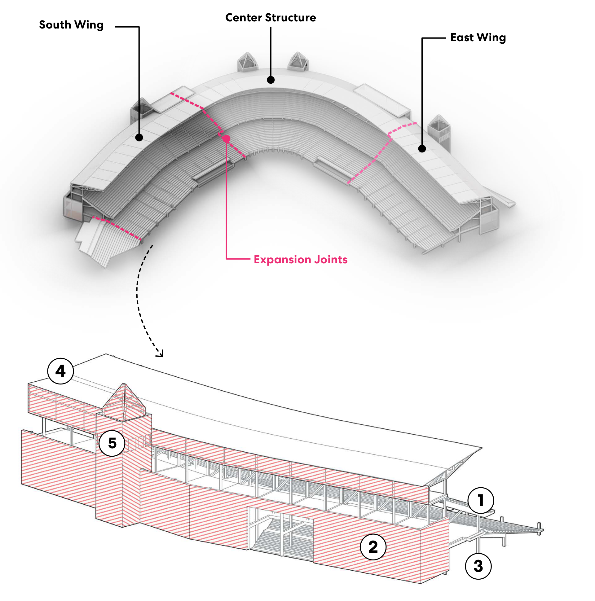
The decision to preserve a segment of Smith’s Ballpark was determined through a structural assessment and the collective desire to celebrate an important part of Salt Lake City’s history.
1
Structural Framing System
Smith’s Ballpark has a main structural framing system of cast-in-place (CIP) concrete bearing walls and steel framing and columns with precast risers in the elevated seating area, composite steel deck on the second and third floors, and metal deck on steel trusses for the high roof. The lateral force resisting system of the structure is special concrete shear walls at the ground level, and special steel moment frames at elevated levels.
2
Non-Load Bearing Elements
The ground floor consists of Infill, non-load bearing concrete masonry unit (CMU) walls. The CMU can be removed to provide greater ground floor transparency.
3
Cast-In-Place Concrete
Underneath the first level of precast seating risers there are cast-in-place concrete tunnels comprised of retaining walls that lead to the field and dugouts.
4
Expansion Joints
Smith’s Ballpark is divided into three areas, named the south wing, center structure, and east wing. It has three levels, the ground level, second floor (concourse area), and the third floor (suite level). The south and east wings are open-air areas where most of the seating is located. The center structure contains enclosed, suite-style seating. These three areas are structurally isolated with expansion joints which enables partial demolition.
5
Architectural Elements Preservation
The adaptive reuse of the building will aim to preserve key architectural elements while exploring opportunities for repurposing them either on-site or at other locations throughout the city. A notable example is the commissioned etched glass installation in the stadium’s towers entitled, ‘Lanterns of Salt Lake City Baseball’, designed by Paul Heath and William Littig.
Scroll horizontally to inspect the diagram.
Diagram description
The upper plan shows the South Wing, Center Structure, and East Wing separated by Expansion Joints. In the lower exploded view, marker 1 points to east-side framing, marker 2 to front CMU infill, marker 3 to the concrete tunnels below seating, marker 4 to the roof structure, and marker 5 to the tower. The detached roof and framing are shown above the existing stadium structure.